555 Timer Schematic Symbol / Results Page 343 About Speed Control By Ic Searching Circuits At Next Gr / For example 555 pin 8 at the top for the +vs supply, 555 pin 3 output on the right.
byAdmin-
0
555 Timer Schematic Symbol / Results Page 343 About Speed Control By Ic Searching Circuits At Next Gr / For example 555 pin 8 at the top for the +vs supply, 555 pin 3 output on the right.. I am using a 12v 2.7ah nimh battery and i am using 4 (4.5v) solar panels in series with a power rating of 1.5 w (each panel) and current rating of 0.334. To make the 555 timer circuit you will also need several other components. When drawing a circuit diagram, always draw the 555 as a building block, as shown below with the pins in the following locations. With the left mouse button still held down, move the mouse to drag the symbol onto the circuit. This makes it easier to read the schematic diagram.
Finally, release the mouse button when the circuit symbol is in the required position. It monitors the charging of the timing capacitor in astable and monostable circuits. Resistors are manufactured over a very large range of values from 1mω to 1kω to 1mω. Its name is derived from three 5k ohm resistors ,connected in series used in it.the timer ic can produce required waveform accurately. The circuit symbol for a 555 (and 556) is a box with the pins arranged to suit the circuit diagram:
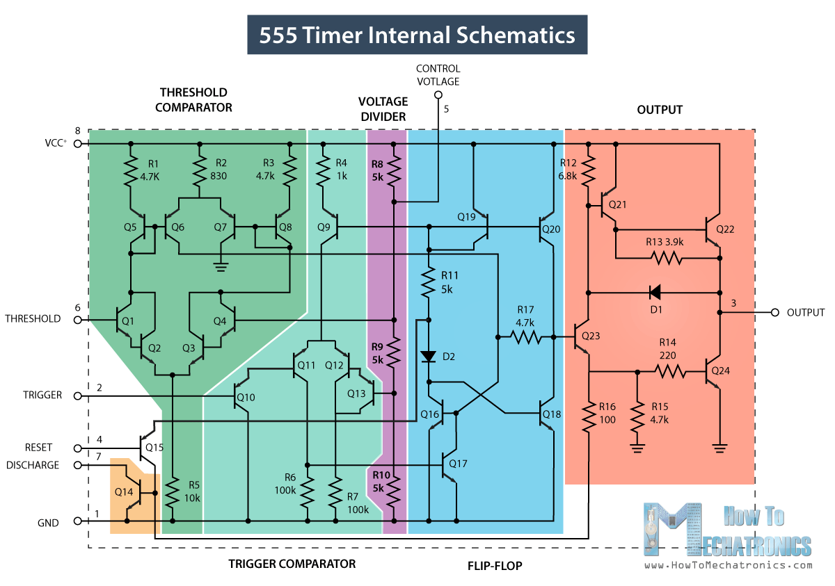
555 Timer Ic Working Principle Block Diagram Circuit Schematics from howtomechatronics.com The power of a resistor can be derived from general electric power formula: Nand gate conversion & example. In monostable mode, the duration for which the pin 3 would remain high, is given by the below formulae: I am using a 12v 2.7ah nimh battery and i am using 4 (4.5v) solar panels in series with a power rating of 1.5 w (each panel) and current rating of 0.334. The 556 shares the power pins. The circuit symbol for a 555 (and 556) is a box with the pins arranged to suit the circuit diagram: The circuit symbol for a 555 (and 556) is a box with the pins arranged to suit the circuit diagram: The circuit symbol for a 555 (and 556) is a box with the pins arranged to suit the circuit diagram:
Now both can be associated to define a component.
It was commercialized in 1972 by signetics. A type of variable capacitor is the trimmer capacitor that is small in size. 555 timer ic testing circuit and its working from www.electronicshub.org if you look closely, you will find the '.' symbol on digital pin 3,5,6,9,10, and 11. Now the schematic symbol and pcb symbol are created for the 555 timer. Derivatives provide two ( 556) or four ( 558) timing circuits in one package. Awesome 555 timer ic projects · 1. Used to vary the capacitance by turning the knob. Also, 555 timer is used to generate an oscillating pulse. With the left mouse button still held down, move the mouse to drag the symbol onto the circuit. In monostable mode, the duration for which the pin 3 would remain high, is given by the below formulae: Under the library manager\component tab, select wizard and create a component by assigning the schematic symbol and pcb symbol in the dialog with the pin assignment and click the finish button. Here, with the help of the 555 timer ic, we are eliminating the need of manually switching on or off the device. The 556 shares the power pins.
This will help you instantly recognise the function of each pin: Schematic symbols for ic's are often laid out differently to the physical ic. Between the positive supply voltage v cc and the ground gnd is a voltage divider consisting of three identical resistors, which create two reference voltages at 1 ⁄ 3 v cc and 2. It does not have pins 1 to 4 on one side and pins 5 to 8 on the other. 500ms is the same as saying 0.5s so by rearranging the formula above, we get the calculated value for the resistor, r as:
555 Repeating Timer Circuit Diagram Circuit Diagram Timer Electronics Circuit from i.pinimg.com It was designed in 1970 by hans r. Connects to the 0v power supply. A monostable 555 timer is required to produce a time delay within a circuit. Between the positive supply voltage v cc and the ground gnd is a voltage divider consisting of three identical resistors, which create two reference voltages at 1 ⁄ 3 v cc and 2. 555 timer was first introduced by signetics corporation in 1971 as se555/ne555. Resistors are manufactured over a very large range of values from 1mω to 1kω to 1mω. A model consists of a subcircuit and a symbol. In this project, we are using 555 timer ic to create various timer circuit like 1 min timer circuit, 5 min timer circuit, 10 min timer circuit, and 15 min timer circuit.
But if you don't, or you think the people reading the schematic won't, then you can draw some or all of the block diagram inside the part.
But if you don't, or you think the people reading the schematic won't, then you can draw some or all of the block diagram inside the part. It does not have pins 1 to 4 on one side and pins 5 to 8 on the other. This circuit uses very basic components like 555 timer and 4017 counter. The power of a resistor can be derived from general electric power formula: 555 timer ic testing circuit and its working from www.electronicshub.org if you look closely, you will find the '.' symbol on digital pin 3,5,6,9,10, and 11. Octopart is the preferred search engine for electronic parts. The schematic symbol for the 555 timer ic is not drawn to the layout of the physical 555 ic. When drawing a circuit diagram, always draw the 555 as a building block, as shown below with the pins in the following locations. Connects to the 0v power supply. The 556 timer ic has 2 timing circuits dual timer, while the 558 timer ic has a total of 4 timing circuits. Pin configuration of the 555 timer here is the identification for each pin: The 556 shares the power pins. The circuit diagrams on this website show a 555, but they could all be adapted to use one half of a 556.
The 556 timer ic has 2 timing circuits dual timer, while the 558 timer ic has a total of 4 timing circuits. The 555 timer is a simple integrated circuit that can be used to make many different electronic circuits. With the left mouse button still held down, move the mouse to drag the symbol onto the circuit. 500ms is the same as saying 0.5s so by rearranging the formula above, we get the calculated value for the resistor, r as: This circuit shows an intruder alarm using 555.
555 Timer Ic Wikipedia from upload.wikimedia.org This circuit shows an intruder alarm using 555. This will help you instantly recognise the function of each pin: Awesome 555 timer ic projects · 1. Set up a 555 timer circuit in monostable mode. In monostable mode, the duration for which the pin 3 would remain high, is given by the below formulae: Simple 555 timer circuits & projects. But if you don't, or you think the people reading the schematic won't, then you can draw some or all of the block diagram inside the part. In this project, we are using 555 timer ic to create various timer circuit like 1 min timer circuit, 5 min timer circuit, 10 min timer circuit, and 15 min timer circuit.
With the left mouse button still held down, move the mouse to drag the symbol onto the circuit.
The 555 timer ic is an integrated circuit (chip) used in a variety of timer, delay, pulse generation, and oscillator applications. 555 timer is an industrial standard ic existing from early days of ic. Between the positive supply voltage v cc and the ground gnd is a voltage divider consisting of three identical resistors, which create two reference voltages at 1 ⁄ 3 v cc and 2. The ohm is the symbol of electrical resistance ω. By some estimates, over a billion 555 timer circuits are built every year. It was commercialized in 1972 by signetics. Let us discuss in detail about this circuit. The pin configuration is shown in the figures. The circuit symbol for a 555 (and 556) is a box with the pins arranged to suit the circuit diagram: With this information you will learn how how the 555 works and will have the experience to build some of the circuits below. The use of each pin in the ic is explained below. The power of a resistor can be derived from general electric power formula: The 555 timer ic is an integrated chip used in a variety of timer, pulse generation, and oscillator applications.
The circuit diagrams on this website show a 555, but they could all be adapted to use one half of a 556 555 timer schematic. The circuit symbol for a 555 (and 556) is a box with the pins arranged to suit the circuit diagram: